Description
● Mode Conditioning Patch Cable (MCP)
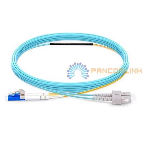
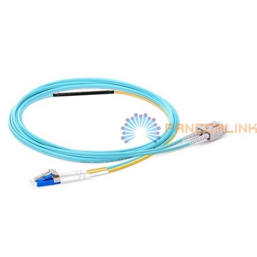
Compliant with IEEE 802.3z standard, MCP Cable is specially used for singlemode and multimode interconnection and applied over multimode plants in Gigabit Ethernet. Operating at 1300nm and designed to prevent modal dispersion, these cables are centerline offset spliced in a manner which the cores do not align center-to-center, allowing the transition from singlemode to multimode. Mode Conditioning Patch Cable utilizes both singlemode and multimode fiber enabling a singlemode signal to be correctly sent through a multimode network. For this application, the singlemode end of a mode conditioning cable should always be connected to the equipment side, while the multimode end should be connected to the plant side. PancomLink offers Mode Conditioning Patch Cables with a variety of options, from all types of connectors to different fiber modes to different jackets to different lengths. Available with a variety of fiber optic connectors for your convenience including: LC/UPC, SC/UPC, FC/UPC, ST/UPC, LC/APC, SC/APC, FC/APC, and MTRJ.

● Features:
►Eliminates issues related to Differential Mode Delay (DMD);
►Compliant with IEEE 802.3z;
►Rugged offset closure with consistent offset;
►Low Insertion Loss;
►PC, UPC, APC polish types.
● Application:
►Gigabit Ethernet 1000Base-LX (1300nm wavelength);
►Recommended for multimode cable runs greater than 50 feet;
►Long Haul to Short Haul LX Gigabit Systems;
►Metropolitan Area Systems;
►Local Area Networks;
►Data Center.
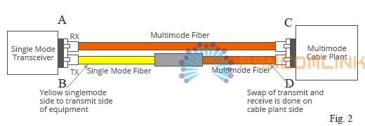
● Specification (Notes:A B C and D,corresponding to A B C and D on Fig.2):
|
Transmission Direction |
Testing Wavelength |
Insertion Loss |
|
DuB |
850nm--1300nm |
Max 0.30dB |
|
BuD |
850nm--1300nm |
Max 0.30dB |
|
CuA |
850nm--1300nm |
15.0dB(50/125um) 18.0dB(62.5/125um) |
|
AuC |
850nm--1300nm |
Max 0.30dB |
|
CuA |
1310nm--1550nm |
2.10dB(50/125um) 2.60dB(62.5/125um) |
|
Return Loss |
APC 60.0dB/UPC 50.0dB |
35.0dB |
|
Durability |
1000 mating |
Typical 0.20dB |
|
Operating Temperature |
-40℃ to +85℃ |
|
How the Mode Conditioning Patch Cable Works
The need for this conditioning fiber optic patch cable is due to the single-mode launch nature of the-LX or long-wave(1300nm)transceiver modules used for Gigabit Ethernet. Launching a single-mode laser into the center of a multimode fiber can cause multiple signals to be generated that confuse the receiver at the other end of the fiber. In that case,a mode conditioning patch cable eliminates these multiple signals by allowing the single-mode launch to be offset away from the center of a multimode fiber. This offset point creates a launch that is similar to typical multimode LED launches.(see diagram below)

How to Install the Mode Conditioning Cable
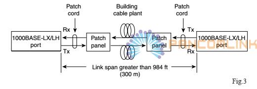
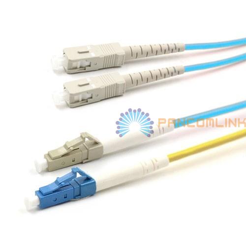
If your gigabit LX switch is equipped with SC or LC connectors, please be sure to connect the yellow leg (singlemode) of the cable to the transmit side, and the orange leg (multimode) to the receive side of the equipment. It is imperative that this configuration be maintained on both ends. The swap of transmit and receive can only be done at the cable plant side. (see diagram below)
Things to Know When Using Mode Conditioning Patch Cables
Mode conditioning patch cable are usually used in pairs. Which means that you will need a mode conditioning patch cable at each end to connect the equipment to the cable plant. Generally, Mode Conditioning patch cables are required for link distances greater than 984 feet (300 meters).
